Back to Kemp Acoustics Home


Next: Numerical implementation
Up: Review of input impedance
Previous: The radiation impedance matrix
Contents
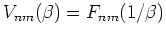
The equations for projection of the impedance matrix
were derived in section 2.6.
Remember that the labels
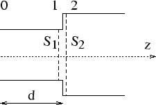
(0), (1) and (2) refer to planes 0, 1 and 2 in figure 4.1.
Figure 4.1:
Detail of a waveguide consisting of straight sections of length  joined discontinuously
 |
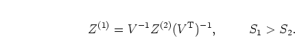
By way of summary, the equation for projection across a discontinuity is
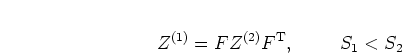 |
(4.3) |
where
 ,
,
 are the cross-sectional areas and
 |
(4.4) |
The projection matrices are given by
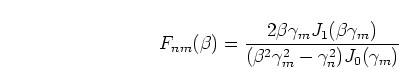 |
(4.5) |
where
 with
with  and
and
 .
.
The equation for projection through a distance is (N.B. This is a correction to the original version of my thesis
and D2 is given in equation (2.41))
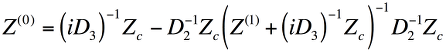 |
(4.6) |
where
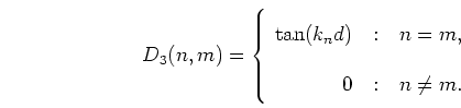 |
(4.7) |
Here
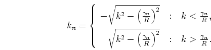 |
(4.8) |
is the wavenumber of the  th mode along the tube neglecting the effect of
losses; the corresponding expression for lossy propagation
is given in section 2.4.1.
th mode along the tube neglecting the effect of
losses; the corresponding expression for lossy propagation
is given in section 2.4.1.
 is the th zero of the Bessel function
  as tabulated in
appendix A.
as tabulated in
appendix A.
Back to Kemp Acoustics Home
Next: Numerical implementation
Up: Review of input impedance
Previous: The radiation impedance matrix
Contents
Jonathan Kemp
2003-03-24