Back to Kemp Acoustics Home


Next: Measuring longer objects
Up: Improvements to pulse reflectometry
Previous: Introduction
Contents
Physically, having a dc tube between the source tube and object under
test is inconvenient. Also the join between source tube and dc tube will not
be perfectly smooth, so a small reflection will be present
at the start of the input impulse response. As discussed in section
5.8 the result is that only half of the available two
milliseconds in the input impulse response data is used in the dc offset
calculation. As an alternative we present
a new method described as the virtual dc tube method [62]. The effect
of the dc tube is simulated by starting recording
the reflections from the object under test 2ms earlier, using a
digital filter (see section 5.4.2) to add the losses that would
have occurred if the sound had travelled across a dc tube.
In effect, the last 40cm of the source tube has
been turned into a virtual dc tube, perfectly joined onto the source tube.
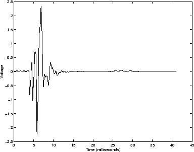
Notice how about 2ms into the dc tube method reflections in figure
5.11 there was a small reflection from the join between the source
tube and the dc tube. The object reflections measured using the virtual dc
tube method from figure 7.1 show that the problem
has been avoided entirely.
Figure 7.1:
Object reflections using virtual dc tube
 |
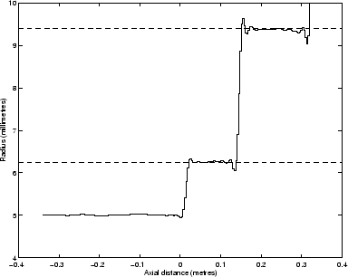
A bore reconstruction achieved using the virtual dc tube method is shown in
figure 7.2. The reconstruction is much the same as
that achieved using the dc tube method (see figure 5.12)
except that the small error of about 0.1mm in the average value of the radius
of the last cylindrical section is absent in the new method. Because the
frequency bandwidth of the measurement is not altered, the oscillations at
the changes of cross-section and at the open end are of the same size
irrespective of whether the virtual dc tube method is used.
Figure 7.2:
Reconstruction of test object consisting of stepped cylinders
 |
Back to Kemp Acoustics Home
Next: Measuring longer objects
Up: Improvements to pulse reflectometry
Previous: Introduction
Contents
Jonathan Kemp
2003-03-24